Composite beams and slabs
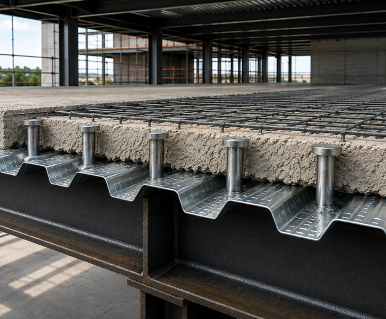
They connect the steel section to the slab so that both elements work as a single composite structural system.
Supply and manufacturing for industrial applications
AWS D1.1 · Type B
Welded elements that create the mechanical connection between steel sections and concrete to transfer shear forces in composite systems.
Main application
Composite beams and slabs
Technical reference
The connector, its weld, the section, the deck and the concrete must all match the project detail and procedure.
Structural connector in accordance with the reference given in AWS D1.1.
Approximately 450 MPa, according to the product technical guide.
Approximately 350 MPa for the low-carbon steel indicated.
Ties the steel section to the concrete slab and limits relative slip.
Composite action
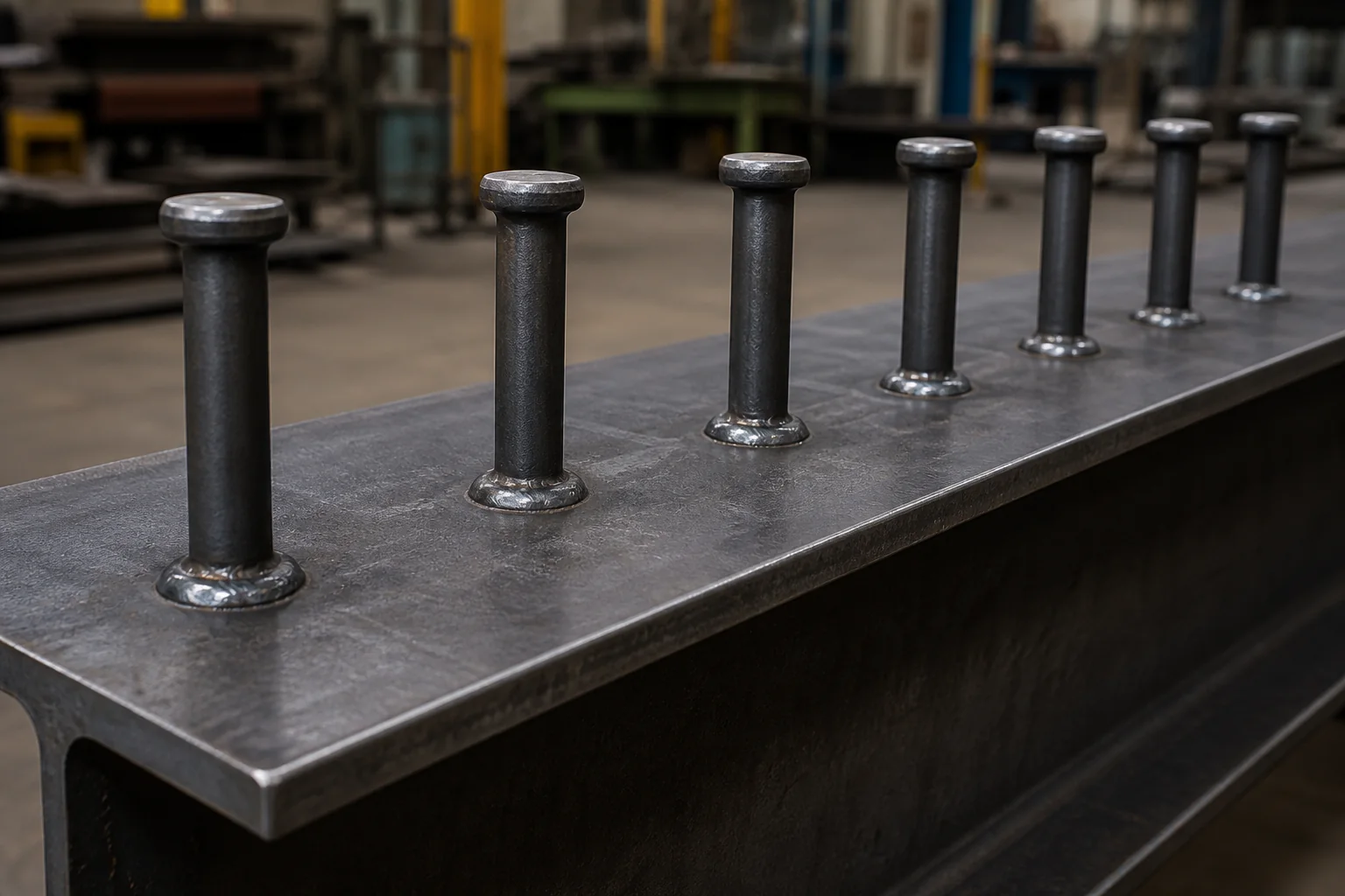
The stud head develops anchorage inside the concrete while the welded end ties the connector to the steel element.
Receives the connector in the position set out in the structural drawing.
Ties the shank to the section through a qualified stud welding procedure.
Deck geometry and reinforcement govern the layout and installation.
Encases the connector head and completes the transfer mechanism.
Applications
They connect the steel section to the slab so that both elements work as a single composite structural system.
Used in steel–concrete configurations where the project requires controlled transfer of shear forces.
They can also form part of anchoring details and embedded elements defined by the project engineering.
Engineering and the installation procedure govern how the connector is defined.
Confirm diameter, length before welding and the required finished height according to the structural detail.
Review section thickness and geometry, the presence of metal deck and the position of each connector.
Installation must follow the procedure, equipment, ferrule and qualification defined for the application.
The project must set out weld controls, layout, quantity and the applicable acceptance criteria.
Technical support
Share diameter, length, quantity, structural drawing, section, deck and the intended procedure. Our technical team will review the requirement.